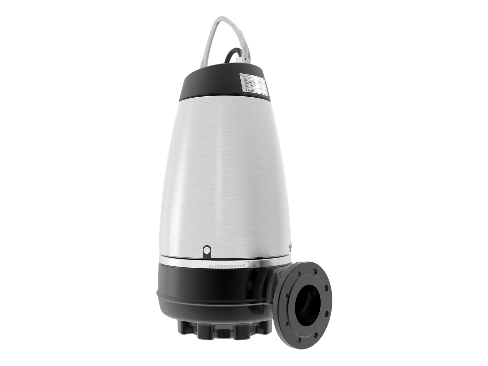
Key features
The jacket cools the motor internally, which is what makes the pump suitable for dry as well as submerged installation without external cooling.
Dry, vertical or horizontal; submerged on an auto-coupling; or submerged free-standing on a ring stand.
Grundfos ticks the S-tube build, not the free-flow one, for a relatively high number of operating hours.
Solids pass whole, through a spherical passage of 50, 65, 80 or 100 mm depending on the pump type.
Both seals come out as one cartridge, with a SiC/SiC primary and a carbon/ceramics secondary.
Grundfos states the entire range is available in explosion-proof versions, certified by Dekra.
About the Grundfos SE
The Grundfos SE is a submersible sewage pump that does not have to be submerged. Grundfos builds it for municipal network pumping stations, inlet pumping stations and clarification pits at treatment works, stormwater stations, public and residential buildings, and factories. It takes wastewater with a high fibre content, drainage and surface water, domestic and municipal wastewater, industrial wastewater, and process and cooling water.
The range splits by impeller. The SE1 carries the S-tube impeller, which Grundfos describes as the only impeller in the wastewater market that compromises neither efficiency nor free passage. The SEV carries the SuperVortex free-flow impeller, which sits back out of the flow for the dirtiest, most fibre-laden media. Both are covered by the same Range 48 data booklet, and both run on the same 1.1 to 11 kW motor platform: IEC IE1 motors of 1.1, 1.3, 1.5, 2.2, 3, 4, 5.5, 6, 7.5, 9.2 and 11 kW, in 2- or 4-pole form depending on size. Grundfos's performance overview shows a larger SE range of 9 to 30 kW above this one.
The two hydraulics reach different corners of the same envelope. Grundfos gives the SE1 a maximum flow of 83 l/s against a maximum head of 27 m, and the SEV 40 l/s against 44 m; both work to a maximum operating pressure of 6 bar and a liquid temperature of 0 to 40 °C. The S-tube shifts volume; the free-flow lifts. Check the duty point before you settle the impeller on the medium alone.
Channel Pumps supplies and sizes the SE. Send us the duty, the medium, the largest solid the pump has to pass and whether the station is wet or dry, and we come back with the impeller, the outlet, the materials, the controls and the certification specified.
How the Grundfos SE works
The SE is a close-coupled submersible pump: a watertight, fully encapsulated motor sits directly above the wet end, and a double mechanical cartridge shaft seal separates the two. The primary face is SiC/SiC, the secondary carbon/ceramics, and both lift out together as one cartridge, so the seal cannot be fitted misaligned. Main bearings are double-row angular contact, support bearings single-row deep-groove, all greased for life.
The difference from a plain submersible is the cooling jacket. The motor is cooled internally by the jacket rather than by the liquid around the pump housing, which is why Grundfos lists the SE as suitable for dry installation without separate motor cooling. In S1 continuous operation the pump housing still has to be completely submerged, but the pump itself does not need a wet well to survive.
SE or SL: the difference is where the pump can stand
The SE and the SL look like the same pump, and in most respects they are: same two impellers, same 1.1 to 11 kW motors, same 50 to 100 mm free passage. Grundfos's own data booklets separate them on one line each — the list of installation types the pump is available for.
| SE (SE1 / SEV) | SL (SL1 / SLV) | |
|---|---|---|
| Installation types Grundfos lists | Dry installation, vertical or horizontal; submerged on auto-coupling; submerged free-standing on ring stand | Submerged on auto-coupling; submerged free-standing |
| Motor cooling | Cooling jacket, internal, no external cooling needed | No cooling jacket in the smartdesign feature list |
| Impellers | S-tube (SE1) or SuperVortex (SEV) | S-tube (SL1) or SuperVortex (SLV) |
| Motors | 1.1 to 11 kW, Range 48 | 1.1 to 11 kW, Generation C |
| Free passage | 50 to 100 mm | 50 to 100 mm |
Read that as a station question rather than a pump question. If the pump hangs on guide rails in a wet well, the SL does the same job on the same hydraulics, and the SE's cooling jacket is capability you have paid for and will never use. Specify the SE where the pumps have to stand in a dry chamber beside the well: a deep station, a confined space you would rather staff did not enter, or pumps that must be reachable without lifting them out of sewage. That is the one installation type only the SE has on its list.
The choice between the SE1 and the SEV is a separate one, and it turns on the medium. Grundfos's selection table gives the SE1 dry solids content up to 3% and the SEV up to 5%; it puts the SEV alone against a relatively high content of fibres and solids, and against industrial process water with fibres and solids; and it ticks the SE1, not the SEV, for a relatively high number of operating hours. So the S-tube is the pump for a station that runs hard on ordinary sewage, and the free-flow is the pump for media that would defeat it.
Materials, sensors and hazardous areas
The standard build is cast iron: pump housing, impeller, motor top, bearing covers and oil chamber cover in EN-GJL-250, with an aluminium stator housing and a stainless steel clamp between motor and pump housing. Three stainless variants sit above it, and each one widens the permitted pH band. The standard cast iron build takes 6.5–14. A stainless impeller (Q) takes 6–14, a complete pump in EN 1.4408/1.4301 (R) takes 1–14, and a stainless pump in EN 1.4517/1.4539 (D) takes 0–14. Where the pH fluctuates rather than sitting steady, Grundfos widens the cast iron and Q bands to 4–14. Everything is powder painted NCS 9000N black, gloss code 30, at 100 μm.
Thermal switches in the stator windings are standard. Beyond that you can specify a Pt1000 in the windings for stator temperature, a moisture switch in the motor chamber, and a water-in-oil sensor in the oil chamber that measures water content from 0 to 20% and reports it to an IO 113 module — the sensor that tells you a shaft seal is failing before it floods the motor. Sensor pumps need no extra cable.
On certification, be specific about the build. Standard SE1 and SEV pumps are tested by VDE, and the standard variants are approved by TÜV Rheinland (LGA) under the Construction Products Directive to EN 12050-1 or EN 12050-2 as stated on the nameplate. The explosion-proof versions are certified by Dekra under ATEX (EU) KEMA 04ATEX2201X, IECEx DEK 21.0017X and UKEX DEKRA 22UKEX0011X, and are classified CE 0344 II 2 GD Ex db eb h mb IIB T4/T3 Gb; Ex h mb tb IIIC T135 °C/200 °C Db. That marking belongs to the Ex builds, not to the range. The T3/200 °C figures apply to pumps run on a frequency converter; T4/135 °C applies to direct drive. Tell us the zone and we specify the build.
Specifications
| Pump types | SE1 (S-tube impeller); SEV (SuperVortex free-flow impeller) | |
|---|---|---|
| Motor power | 1.1, 1.3, 1.5, 2.2, 3, 4, 5.5, 6, 7.5, 9.2 and 11 kW | IEC IE1, 2- or 4-pole depending on size; Range 48 |
| Maximum flow | 83 l/s (SE1); 40 l/s (SEV) | |
| Maximum head | 27 m (SE1); 44 m (SEV) | |
| Maximum operating pressure | 6 bar | |
| Free passage | 50 to 100 mm spherical | 50, 65, 80 or 100 mm by pump type |
| Outlet | DN65 to DN150, cast iron PN 10 flange | to EN 1092-2 |
| Installation | Dry, vertical or horizontal; submerged on auto-coupling; submerged free-standing on ring stand | |
| Operation | S1 continuous when the pump housing is completely submerged | dry installation needs no separate motor cooling |
| Liquid temperature | 0 to 40 °C | up to 60 °C for a maximum of one hour, non-Ex versions only |
| pH range | 6.5–14 standard cast iron; 6–14 (Q), 1–14 (R), 0–14 (D) | 4–14 on the cast iron and Q builds where the pH fluctuates |
| Maximum starts per hour | 20 | |
| Maximum installation depth | 20 m | |
| Enclosure and insulation class | IP68; insulation class F (155 °C), temperature rise class F (105 °C) | |
| Shaft seal | Double mechanical cartridge seal, SiC/SiC primary, carbon/ceramics secondary | |
| Materials | Cast iron EN-GJL-250 wet end and motor top; aluminium stator housing; stainless steel clamp | stainless variants Q, R and D available |
| Finish | Powder paint NCS 9000N black, gloss code 30, 100 μm | |
| Cable | 10 m as standard | other lengths and screened EMC cable for converter duty on request |
| Explosion protection | CE 0344 II 2 GD Ex db eb h mb IIB T4/T3 Gb; Ex h mb tb IIIC T135 °C/200 °C Db | explosion-proof versions only, certified by Dekra |
| Performance test | ISO 9906:2012, grade 3B as standard |
Channel Pumps sizes and supplies the Grundfos SE. Tell us the flow, the total head, the medium and its solids and fibre content, the largest solid the pump must pass, whether the station is wet or dry, and whether the area is classified, and we specify the impeller, the outlet, the materials, the sensors and the controls.
Documents & downloads
Related pumps
View all →
Frequently asked
What is the Grundfos SE pump used for?
The SE moves sewage and wastewater in municipal network pumping stations, treatment-works inlet stations and clarification pits, stormwater stations, buildings and industry. Grundfos rates it for wastewater with a high fibre content, drainage and surface water, domestic and municipal wastewater, industrial wastewater, and process and cooling water.
What is the difference between the Grundfos SE and SL?
The installation types. Grundfos lists the SE for dry installation, vertical or horizontal, as well as submerged on an auto-coupling or free-standing, and credits the cooling jacket for it. The SL data booklet lists two installation types, both submerged. The impellers, the 1.1 to 11 kW motors and the 50 to 100 mm free passage are the same.
Can the Grundfos SE be dry-installed?
Yes. A cooling jacket cools the motor internally, so Grundfos lists the SE as suitable for dry installation without separate motor cooling, mounted vertically or horizontally. For S1 continuous operation the pump housing must be completely submerged.
What is the difference between the SE1 and the SEV?
The impeller. The SE1 uses the S-tube, and Grundfos ticks it for a relatively high number of operating hours and dry solids content up to 3%. The SEV uses the SuperVortex free-flow impeller, takes dry solids up to 5%, and is the one Grundfos lists for a relatively high content of fibres and solids.
How big a solid will a Grundfos SE pass?
The free spherical passage is 50 to 100 mm depending on the pump type, so 50, 65, 80 or 100 mm. The type key states it directly, because the first number after SE1 or SEV is the maximum solids size in millimetres. Confirm the figure for a given model with Channel Pumps.
Is the Grundfos SE available for hazardous areas?
Grundfos states the entire range is available in explosion-proof versions. Those builds are certified by Dekra under ATEX (EU) KEMA 04ATEX2201X, IECEx DEK 21.0017X and UKEX DEKRA 22UKEX0011X, and marked CE 0344 II 2 GD Ex db eb h mb IIB T4/T3 Gb. Tell us the zone.
- 1Grundfos — SE/SL wastewater pumps
- 2Grundfos — SE1 submersible wastewater pumps
- 3Grundfos — SEV submersible wastewater pumps
- 4Grundfos — SE1, SEV pumps Range 48, 1.1 to 11 kW data booklet
- 5Grundfos — SE1 50, 80, 100 and SEV 65, 80, 100 installation and operating instructions
- 6Grundfos — SL1, SLV pumps Generation C, 1.1 to 11 kW data booklet