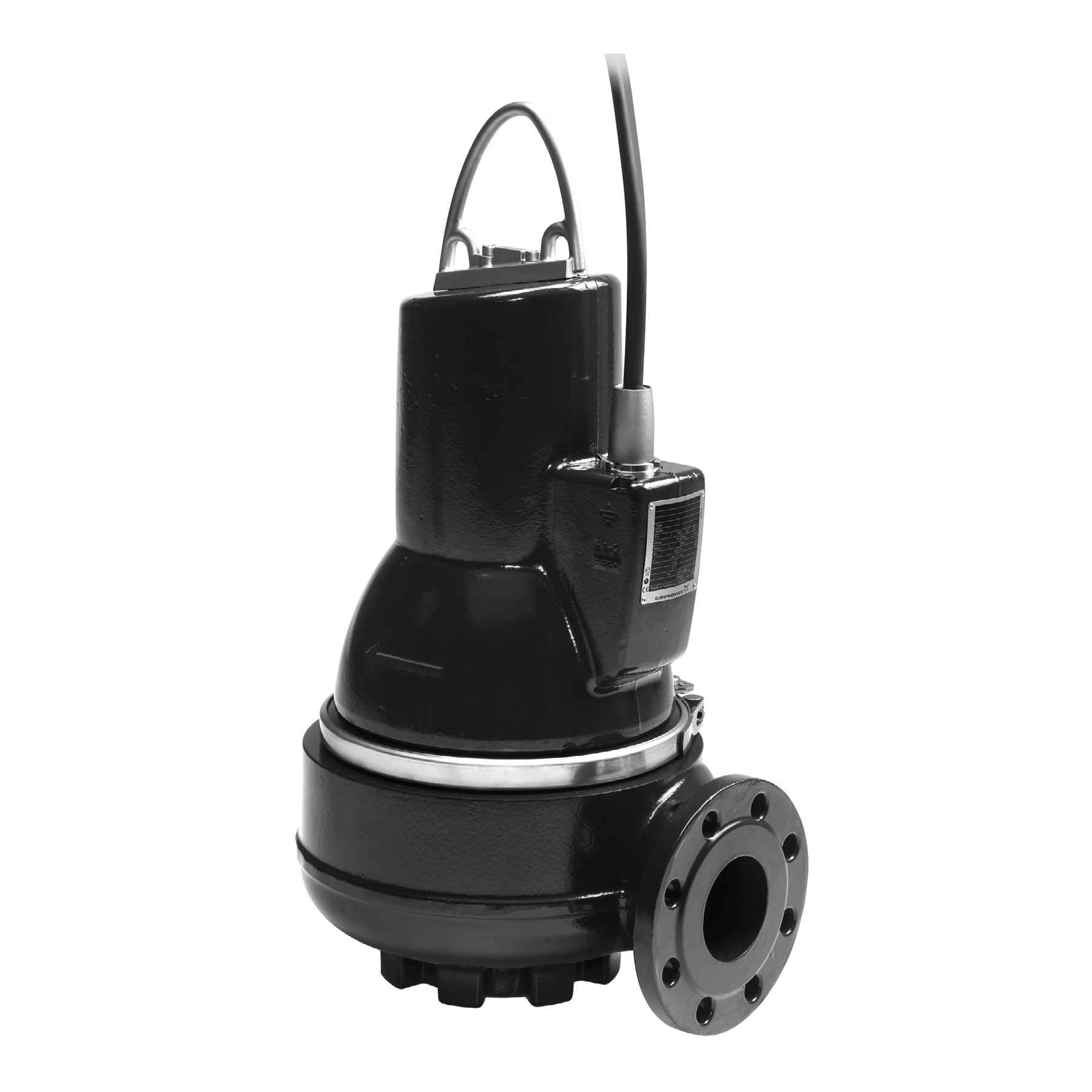
Key features
A near-round through passage that holds efficiency and free passage at the same time. The SL1 reaches 83 l/s and 26 m.
The impeller sits back out of the flow, so fibre and gassy sludge pass with little contact. The SLV reaches 40 l/s and 44 m.
Two- or four-pole depending on size, built for frequency-converter duty from 30% to 100% speed.
Primary seal SiC/SiC, secondary carbon/ceramic, both in one cartridge. Shorter to fit and harder to fit wrongly.
The optional WIO sensor reads 0–20% water content in the oil chamber and signals the IO 113 module before the seal takes the motor with it.
Explosion-proof builds hold KEMA08ATEX0125X and IECEx KEM08.0039X, marked CE 0344 II 2 G Ex c d IIB T4 Gb, or Ex c d mb IIB T4 Gb on a sensor version.
About the Grundfos SL
The Grundfos SL is a submersible wastewater pump built for wet wells. Grundfos specifies it for domestic, industrial and municipal wastewater, for drainage and surface water, and for process and cooling water. It is the pump you drop in and forget about, until the screening upstream lets through something it should have caught. The stations it turns up in are municipal network pumping stations, inlet pumping stations at treatment works, primary and secondary clarification, stormwater stations, and the wet wells under public buildings, residential blocks and factories.
The range splits on the impeller, and that is the decision worth getting right. The SL1 carries Grundfos's S-tube impeller and reaches 83 l/s (299 m³/h) against a maximum of 26 m. The SLV carries the SuperVortex free-flow impeller, reaches 40 l/s (144 m³/h), and takes the head up to 44 m. So the SL1 is the higher-flow pump and the SLV is the higher-head pump, which catches people out. If the duty is high flow against modest head, that is SL1 territory. If the medium is rag-laden, fibrous or gassy, or the duty is intermittent with a higher dry solids content, the SLV is the pump even though it costs you flow.
Free passage is set by the size, not by the range, and it runs 50 mm to 100 mm. The model designation tells you both figures: an SL1.100.150 has a 100 mm free spherical passage and a DN150 discharge, and an SL1.50.65 has 50 mm and DN65. Discharge flanges are cast iron to EN 1092-2, PN 10, in DN65, DN80, DN100 and DN150. Wetted parts are cast iron on the standard build, with a stainless steel impeller available on the SLV Q variant.
Motors are IEC IE3 premium efficiency, two- or four-pole depending on the size, from 1.1 kW up to and including 11 kW. Every type in the range is designed for speed control, and Grundfos recommends running a speed-controlled pump between 30% and 100% and keeping flow above 1 m/s so the rising main does not silt up.
Where it is the wrong pump
The SL only goes in wet. Grundfos lists two installation arrangements and both are submerged: on a stationary auto-coupling guide rail system, or free-standing on a ring stand. There is no dry-installed build of the SL, because the surrounding liquid is what cools the motor. A dry-pit station, or a well whose level draws down below the motor in normal operation, wants the SE, which carries a cooling jacket and runs submerged or dry. For the free-flow impeller with a dry install, that combination is the SEV.
The duty cycle constrains the station as tightly as the duty point does. Unless the pump is fully submerged to the top of the motor, it is on S3 intermittent duty: a maximum of 20 starts per hour, running for at most four minutes and stopping for at least six. Explosion-proof pumps get no S3 allowance and must always be fully submerged. A wet well with too little working volume will breach that cycle long before the pump wears out, and the fix is the well, not a bigger pump.
The ceilings are hard ones. 26 m on the SL1 and 40 l/s on the SLV are the ends of the range, and no single pump reaches both. Liquid temperature is 0–40°C, with 60°C permitted for a maximum of three minutes on non-Ex versions only; an explosion-proof pump must never see above 40°C. The standard cast iron build covers pH 6.5 to 14, the SLV Q variant with the stainless impeller goes down to pH 6, and where pH swings around the allowance is 4 to 14. Acidic effluent below that is a different pump in a different material. If the medium is denser or more viscous than water, the motor has to be sized up for it, which usually means moving a frame size rather than accepting the curve you were shown.
And a better pump does not fix rag. What gets called a pump fault on a wastewater station is usually not a selection error. Something upstream changed, or the screening was never doing what the design assumed, and the pump is simply the part of the station that stops first. We have turned down an order for a replacement submersible on exactly that basis: the pump already in the well was a capable solids-handling machine, so a like-for-like swap would have failed the same way. That site needed the rag taken out ahead of the pump. Send us what the water actually carries and how the well fills, and we will tell you whether you have a pump problem before we quote you a pump.
How the Grundfos SL works
The pump sits in the wet well with the motor mounted directly above the wet end, immersed in the wastewater it is moving. Liquid enters the pump housing, the impeller drives it out through the discharge flange and up the rising main, and the surrounding liquid carries the motor's heat away through the housing. On a permanent installation the pump seats itself on an auto-coupling and lifts out on guide rails, so an inspection does not mean breaking pipework or draining the well.
The two impellers
The S-tube impeller in the SL1 is a near-round through passage. Grundfos's claim for it is blunt: it is the only impeller on the wastewater market that compromises neither efficiency nor free passage through the pump. On a conventional channel impeller you buy free passage by giving up efficiency, and you feel that trade every hour the station runs.
The SuperVortex impeller in the SLV works the other way round. It sits back out of the flow path and moves the liquid by the swirl it generates, so solids and fibre travel through the housing with little contact with the impeller itself. You pay for that in efficiency and in flow. What you get back is a pump that keeps running on media that bind a conventional impeller, which is why Grundfos points the SLV at intermittent duty and at liquids with a high content of solids, fibres or gassy sludge.
Cooling and the duty cycle
There are two operating modes, and which one you are in is decided by the liquid level, not by the controller. In S1 continuous operation the pump is covered to the top of the motor, the surrounding liquid takes the heat, and the pump can run without stopping to cool. In S3 intermittent operation the pump is only covered to the bottom of the cable plug, so it runs for a maximum of four minutes, stops for a minimum of six, and starts no more than 20 times an hour.
That is worth checking against your own level settings before you order anything, because a well sized on flow alone will cycle a pump harder than S3 allows. Explosion-proof pumps have no S3 allowance and must always be fully submerged.
Seal, bearings and monitoring
On a wastewater pump the shaft seal is what usually fails first, and it fails because it ran without liquid to lubricate it. Grundfos puts two mechanical seals in the SL, primary SiC/SiC and secondary carbon/ceramic, and packages both into a single cartridge. The cartridge is shorter than a conventional arrangement and it takes the guesswork out of a rebuild, which matters because a seal fitted badly in a wet well fails as reliably as one that was run dry.
Main bearings are double-row angular contact, support bearings are single-row deep-groove, and both are greased for life. The cable enters through a stainless steel plug held by a union nut, filled with polyamide cast around the conductors so moisture cannot track into the motor down the cable core. All cast iron parts get cataphoresis treatment and then 100 μm of black powder paint.
Thermal switches in the stator windings are standard. Three sensor options sit on top of that: a Pt1000 in the windings for stator temperature, a moisture switch in the motor chamber, and a water-in-oil sensor in the oil chamber that measures 0–20% water content and converts it to an analogue signal. All three report to an IO 113 module, which can stop the pump on a fault and reports motor temperature, moisture in the motor, water in the oil and insulation resistance. Sensor versions of the pump need the IO 113 to work properly, and Grundfos supplies it with the pump.
Watch the oil, because it is the early warning on the seal. Grundfos asks for an inspection every 3,000 operating hours or at least annually, more often on muddy or sandy liquid, and an oil change on the same interval. More than 20% extra water in the oil chamber means the shaft seal has gone. On a new pump, or after a seal replacement, check the level and the water content after a week.
Controls
The pump has to be connected to a control box with a motor protection relay of IEC trip class 10 or 15, and class 10 is mandatory for pumps in hazardous locations. For control, Grundfos offers the LC and LCD level controllers in three variants, working on air bells, float switches or electrodes, with LC handling one pump and LCD two with automatic alternation. Above that sits Dedicated Controls, built around a CU 362 unit and IO 351B modules, which controls and monitors one to six wastewater pumps plus a mixer or a flush valve.
Standards and hazardous areas
Standard variants are approved by LGA, a notified body under the Construction Products Directive, to EN 12050-1 or EN 12050-2 as stated on the pump nameplate. Which of the two applies depends on the build, so read the plate rather than assume.
Explosion-proof versions have been tested by KEMA and hold two examination certificates: ATEX KEMA08ATEX0125X and IECEx KEM08.0039X. The classification is CE 0344 II 2 G Ex c d IIB T4 Gb for a direct-drive pump without a sensor, and Ex c d mb IIB T4 Gb with one, where mb is encapsulation to EN 60079-18. T4 drops to T3 where a frequency converter drives the pump, because the converter raises the maximum surface temperature from 135°C to 200°C. Ambient temperature for an explosion-proof pump has to sit between -20°C and +40°C, or 0°C to +40°C if it carries a WIO sensor. Certification applies to a specific build, so send us the zone classification for the station and we will get the certificate for the exact pump from Grundfos before anything is ordered.
Specifications
| Impeller types | S-tube (SL1); SuperVortex free-flow (SLV) | |
|---|---|---|
| Maximum flow, SL1 | 83 l/s (299 m³/h) | range maximum, 50 Hz |
| Maximum head, SL1 | 26 m | range maximum, 50 Hz |
| Maximum flow, SLV | 40 l/s (144 m³/h) | range maximum, 50 Hz |
| Maximum head, SLV | 44 m | range maximum, 50 Hz |
| Maximum operating pressure | 6 bar | |
| Motor output power | 1.1, 1.3, 1.5, 2.2, 3, 4, 6, 7.5, 9.2 and 11 kW | two- or four-pole depending on size |
| Motor efficiency | IEC IE3 | |
| Free spherical passage | 50–100 mm | depends on pump size |
| Discharge flange | DN65, DN80, DN100 or DN150 to EN 1092-2 | cast iron, PN 10 |
| Liquid temperature | 0–40°C | up to 60°C for a maximum of 3 minutes, non-Ex versions only |
| pH value | 6.5–14 | 6–14 on the SLV Q variant; 4–14 where pH fluctuates |
| Wetted materials | Cast iron impeller and pump housing | stainless steel impeller on the SLV Q variant |
| Shaft seal | Double mechanical cartridge seal | primary SiC/SiC, secondary carbon/ceramic |
| Bearings | Double-row angular contact main, single-row deep-groove support | greased for life |
| Enclosure class | IP68 to IEC 60529 | |
| Insulation class | H (180°C) | temperature rise class A (60°C) |
| Supply voltage | 3 x 380–415 V or 3 x 400–415 V, 50 Hz | |
| Operating mode | S3 intermittent, maximum 20 starts per hour | 4 minutes run, 6 minutes stop; S1 continuous when fully submerged to the top of the motor |
| Installation | Submerged, on an auto-coupling guide rail system or free-standing on a ring stand | |
| Speed control | 30–100% speed | Grundfos recommends keeping flow above 1 m/s to avoid sedimentation |
| Motor protection | Thermal switches in the stator windings as standard | Pt1000, water-in-oil sensor and moisture switch optional, reporting to an IO 113 |
| Motor protection relay | IEC trip class 10 or 15 | class 10 is mandatory for pumps in hazardous locations |
| Standards approval | LGA to EN 12050-1 or EN 12050-2 | as stated on the pump nameplate |
| Hazardous area | ATEX KEMA08ATEX0125X; IECEx KEM08.0039X | CE 0344 II 2 G Ex c d IIB T4 Gb, or Ex c d mb IIB T4 Gb with a sensor; T3 in place of T4 on a frequency converter |
| Ambient temperature, Ex versions | -20°C to +40°C | 0°C to +40°C with a WIO sensor |
| Surface treatment | Cataphoresis on all cast iron parts, then 100 μm powder paint | NCS 9000N black, gloss code 30 |
| Standard cable length | 10 m | 15, 20, 25, 30 and 40 m available |
| Noise emission | Below 70 dB(A) | sound power to ISO 3743, calculated at 1 m to ISO 11203 |
| Oil | Shell Ondina 919 or similar | change every 3,000 operating hours or once a year |
Channel Pumps sizes and supplies the Grundfos SL. Send us the flow rate, the total dynamic head, the medium and the largest solid it has to pass, the working volume of the wet well and the starts per hour you expect, and any hazardous-area classification. Those last two decide as much as the duty point does, because they settle whether the pump runs S1 or S3 and whether it has to be an explosion-proof build.
Documents & downloads
Related pumps
View all →
Frequently asked
What is the Grundfos SL pump used for?
The SL is a submersible sewage and wastewater pump for a wet well. Grundfos specifies it for domestic, industrial and municipal wastewater, drainage and surface water, and process and cooling water, in municipal network pumping stations, treatment works inlets and clarification stages, stormwater stations, and the wet wells under buildings and factories.
What is the difference between the SL1 and the SLV?
The impeller, and it moves the duty envelope. The SL1 has the S-tube impeller and reaches 83 l/s against a maximum of 26 m, which suits high flow at modest head, while the SLV has the SuperVortex free-flow impeller, reaches 40 l/s, takes the head to 44 m and is the pump for rag-laden, fibrous or gassy media.
How big a solid can the Grundfos SL pass?
Free spherical passage is 50–100 mm depending on the pump size, and the size is in the designation. An SL1.100.150 passes 100 mm and discharges through DN150; an SL1.50.65 passes 50 mm through DN65.
Can the Grundfos SL be dry-installed?
No. Grundfos lists two installation arrangements for the SL and both are submerged, either on a stationary auto-coupling guide rail system or free-standing on a ring stand, because the surrounding liquid is what cools the motor; for a dry-pit station, the SE runs submerged or dry on a cooling jacket and the SEV does the same with a free-flow impeller.
How many starts per hour can a Grundfos SL take?
A maximum of 20 starts per hour. Unless the pump is fully submerged to the top of the motor it is on S3 intermittent duty, running for no more than four minutes and stopping for at least six, and explosion-proof pumps have no S3 allowance at all because they must always be fully submerged.
Is there an ATEX version of the Grundfos SL?
Yes. Explosion-proof versions have been tested by KEMA and hold ATEX certificate KEMA08ATEX0125X and IECEx certificate KEM08.0039X, marked CE 0344 II 2 G Ex c d IIB T4 Gb, or Ex c d mb IIB T4 Gb with a sensor, and T3 in place of T4 where a frequency converter drives the pump. Certification applies to a specific build, so send us the zone classification and we will get the certificate for the exact pump from Grundfos.
What liquid temperature and pH can the SL handle?
Liquid temperature is 0–40°C, with up to 60°C permitted for a maximum of three minutes on non-Ex versions only. The standard cast iron build covers pH 6.5 to 14, the SLV Q variant with a stainless steel impeller goes down to pH 6, and where pH fluctuates the allowance is 4 to 14.
How often does a Grundfos SL need servicing?
Grundfos asks for an inspection every 3,000 operating hours or at least once a year, and more often if the liquid is very muddy or sandy. Change the oil on the same interval. More than 20% extra water in the oil chamber means the shaft seal has failed, so check the level and water content a week after a new pump or a seal replacement goes in.
- 1Grundfos — SL1 submersible wastewater pumps
- 2Grundfos — SLV submersible wastewater pumps
- 3Grundfos data booklet — SL1, SLV pumps 1.1 to 11 kW, 50 Hz
- 4Grundfos — SL1 and SLV pumps 1.1-11 kW, 50/60 Hz DIN, installation and operating instructions
- 5Grundfos data booklet — SL1, SLV pumps Generation C, 1.5 to 15 hp (1.1 to 11 kW)